Beyond the Bootloader: Bus Pirate Root Adventures
The Bus Pirate is an amazing open-source tool for hardware debugging. It supports a wide range of protocols like SPI, I2C, UART, and JTAG, making it ideal for exploring routers, IoT devices, or any hardware utilizing these common protocols. Once a device is disassembled, several directions open up for hardware exploration. In this post, we’ll focus on assessing the router’s security and attempting to gain root access. Future posts will cover more advanced topics, such as pulling firmware or modifying the boot process.
Before starting we need to make sure the Bus Pirate firmware is up to date.
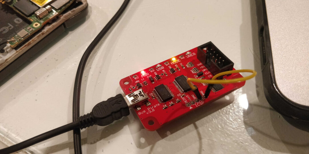
Bus Pirate Setup
The boot loader and firmware can be downloaded from the DangerousPrototypes GitHub page. Or run the git command
$ sudo git clone https://github.com/DangerousPrototypes/Bus_Pirate/
Navigate to the Boot Loader file. (If using Linux)
$ ~/Bus_Pirate/BPv4-bootloader/pirate-loader
Next connect the Bus Pirate via the USB cable and push the update. NOTE: The jumper that needs to be in place to update the firmware and replace the firmware version with preferred option.
$ sudo ./pirate-loader_lnx --dev-/dev/ttyUSB0 --hex-BPv3-firmware-v6.3-r2151.hex
Next we need a terminal based serial communication program to run commands. Minicom is ideal for this. to install and configure minicom to run over USB
$ sudo apt install minicom
$ sudo minicom -s
In the configuration settings setup USB as the serial usb /dev/tty/USB0 and finally save as dfl.
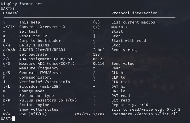
To run the program type minicom in the terminal, if configured correctly any keystroke will cause the led on the Bus Pirate to blink. typing ? in the minicom window will bring up the help menu.
The Fun Begins.
Locate the UART connector on the device. UART has 4 pins: Power, Ground, Tx and Rx.
Once located we need to identify the function of each pin using a multimeter.
Ground: The ground pin can be found by finding a known ground on the device and checking continuity between each of the 4 pins. Only one should have continuity with the motherboard ground.
Power: The power pin can be found by checking voltage between the ground point/pin and one of the 3 other pins. The power pin should have a constant voltage typically between 3v-12v depending on the device.
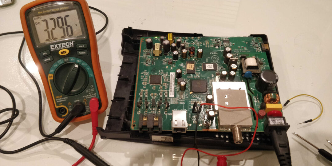
Tx: The transmit pin should have a small spike in voltage typically a very low voltage. This is the data that the device is sending back to read.
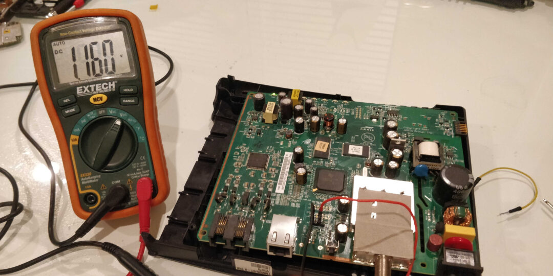
Rx: The receive pin will have no voltage spikes and can be found simply from process of elimination. This pins voltage only spikes when data is sent to the device.
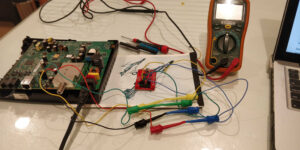
Final connection set up.

Reading The Data
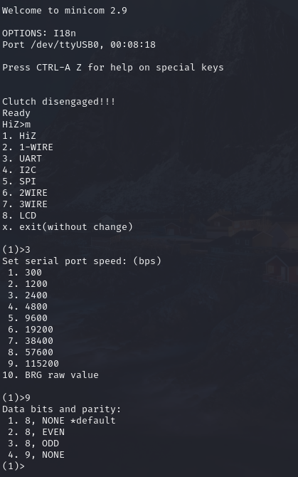
With the Bus Pirate powered and connected to the computer and the modem off we need to finalize our settings. Run minicom and bring up the menu by hitting ‘m’ key. There will be 6 options needed to be set for UART. (The settings are different for each protocol)
- Protocol (3=UART)
- Serial Port Speed (5=9600bps the communication speed can either be found with a little research or by some trial and error)
- Data Bits and Parity (4=None)
- Stop Bits (1=Default)
- Receive polarity (Idle 1= Default)
- Output type (2=Normal)
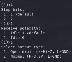
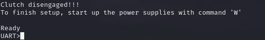
Once settings are configured hit the ‘W’ key to start the UART protocol connection
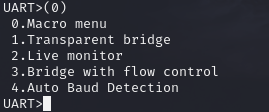
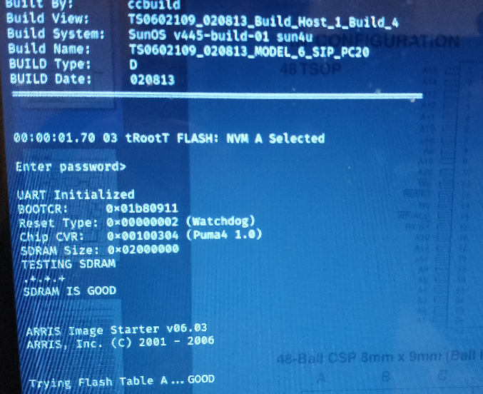
Using transparent bridge mode, live mode or bridge with flow control we can monitor the bios boot process. After the modem is powered a stream of data will start to flow across the screen, keep an eye out for Bios and Build versions as this can lead to finding manuals and default passwords for devices.
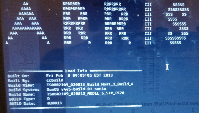
On many IoT devices or routers the user is often presented with a login screen. If that is the case finding root passwords is a simple Google search away since we now have build numbers and OS data. But on occasion after the boot screen loads we are left with no input on the terminal, in that case we need to dig a littler deeper.
Glitching SDRAM
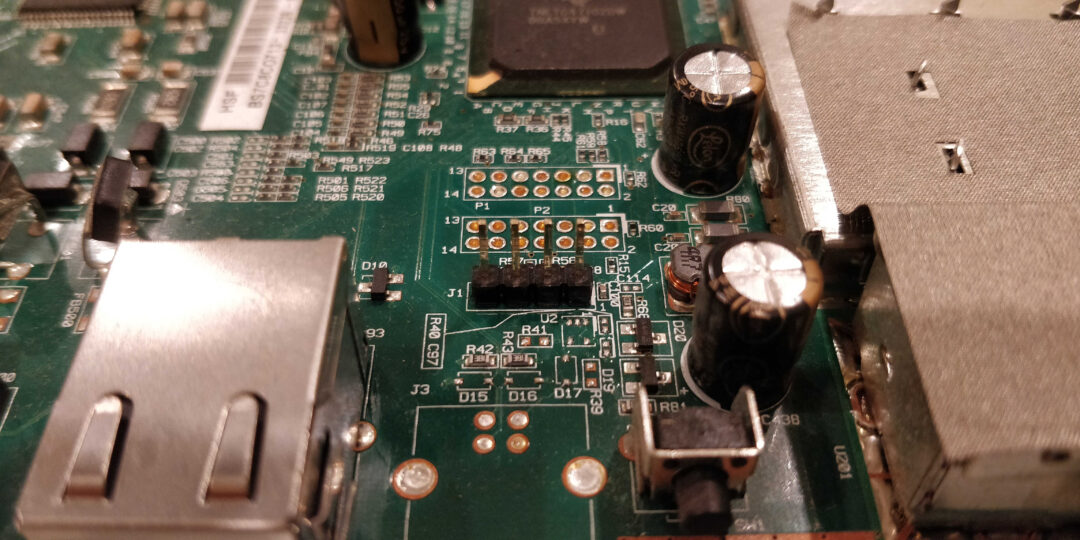
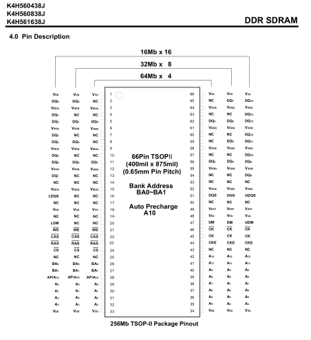
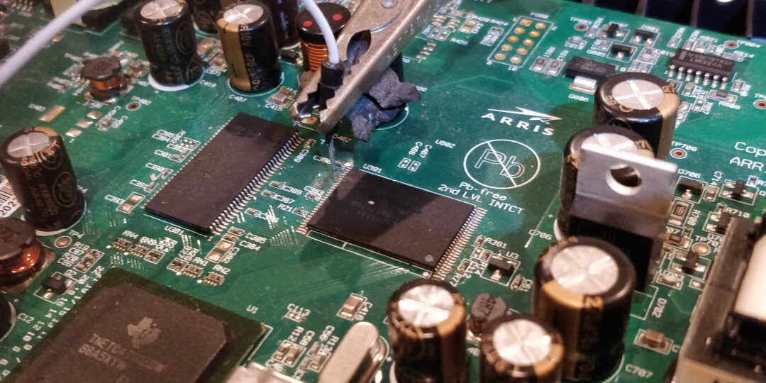
The next step will be to introduce faults in the boot process by shorting I/O pins to ground during the boot process. Note that the results vary but in this case we get just a little closer to root. The first thing is to find the SDRAM chip on the board, from there we find the data sheet for the chip. Next we find the I/O pins see picture below as example.
Once the I/O pins are determined we connect one wire to the ground of the board and the other will probe each I/O pin interrupting the boot process. This takes time since the boot process window to interrupt the boot and create a fault can be a fraction of a second. It is easy to miss and there is more than one I/O pin.
Good things come to those patient and determined. Picture below shows the SDRAM glitch created a fault that jumped to a password screen that was previously blocked.
In the next post, we will attempt to pull the firmware directly from the chip and go further down the rabbit hole.